EMS Loop Tenant Site Configuration Utility
The following will give you guidance with setting up your installation of EMS Loop.
Figure 7 shows the common settings that will be used within EMS Loop. On the Common tab you can configure common settings, start and stop services as well as open logging folders and send logs to Support via FTP.
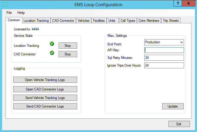
Figure 7
A brief description of the items on the Common tab will follow.
Licensed To – This is the customer number that is configured in the system. This is the customer number that you have been assigned from EMS Loop and that you used during the installation of the services.
Service State -- This area shows the status of the two services required for EMS Loop. Shown in Figure 7, the services are running. If the services were running there would be a red stop sign instead of the green check mark indicating such. There is a start / stop button within the area as well. This button will start the services if stopped and stop the services if running.
Logging – There are four buttons within this area. The buttons are labeled for what they do. When opening logs it will open the Windows file explorer to the log location for the respective services. The “Send” buttons will zip and send the log files to support via FTP.
Misc Settings – This section contains settings required for EMS Loop to function properly. These settings should only be changed if instructed to do so by support. End Point is the website that you’re system is connecting to. API Key is the key you received from EMS Loop and used in the installation. Sql Retry Minutes is the number of minutes that the services will continue to try to connect to the CAD Sql Server, should it becomes unavailable. Ignore trips over hours, this setting will adjust number hours old a run can be in CAD for the Service to look at.
The “Location Tracking” tab as shown in Figure 8 is used to configure which vehicles within your CAD you wish for the services to request GPS data for and update your CAD system with that data. Moving the vehicles from the left column to the right column will enable those vehicles to be tracked. Once enabled the selected vehicles will be updated in your CAD with the most currently available GPS data from the EMS Loop application.
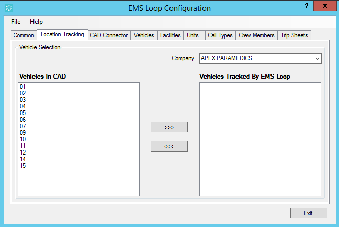
Figure 8
The CAD connector tab is where you configure the vehicles within your CAD for which you want EMS Loop to monitor for runs and send those runs to the EMS Loop mobile application. Moving the vehicles from the left column to the right column will enable the selected vehicles to receive runs on their mobile devices as well as be available in the EMS Loop website.
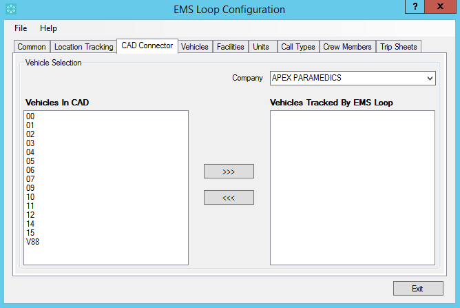
Figure 9
There is some data that needs to be exported to EMS Loop upon initial install for EMS Loop to function. The next few tabs are tabs that enable the export of data from your CAD System into the EMS Loop system. On the “Vehicles” tab as shown in Figure 10, will allow you to import your vehicles into EMS Loop. Select the vehicles you intend to use EMS Loop with on the left and move them to the right column. Once they are in the right column click the export button to export them into the EMS Loop system.
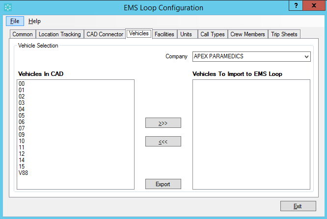
Figure 10
Once they are exported you can validate that they are in EMS Loop through the EMS Loop website. By navigating to the Administration area and then selecting vehicles.

EMS Loop requires your facilities list. On the facilities tab you can export your facilities into EMS Loop by simply clicking the “Update All” button. This will upload all of your facilities into EMS Loop during initial install of the services. After the initial export the services will automatically keep the facilities in sync between EMS Loop and your CAD.
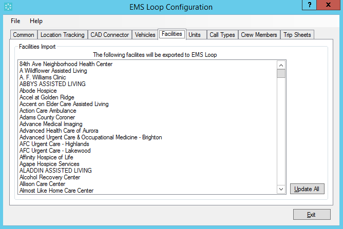
Figure 11
You can validate your facilities in EMS Loop through the website by navigating to Administration → Facilities.

If you use units within your CAD then you’ll need to export those into EMS Loop as well. This can be done on the “Units” tab within the configuration utility. Simply click the Update All button and they will be exported into EMS Loop.
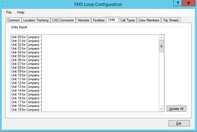
Figure 12
Once the units are exported into EMS Loop the CAD connector services will keep your CAD and EMS Loop units lists in sync.
Call types also must be available in EMS Loop. Once again, simply click the “Update All” button to export your call types from CAD into EMS Loop.
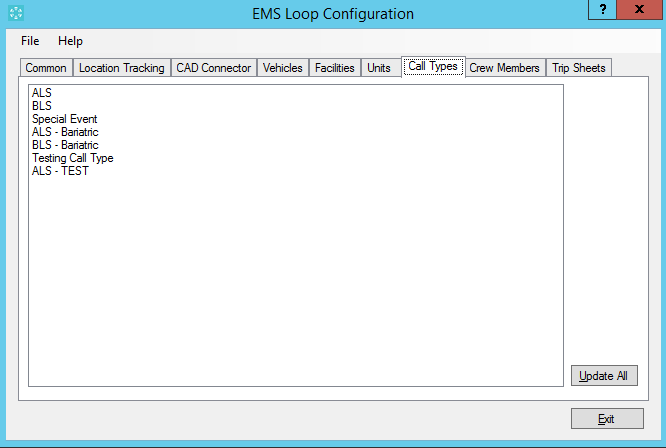
Figure 13
Once again as with all of the other lists, once the lists have been exported the CAD Connector services will keep EMS Loop and your CAD in sync.
Lastly, crew members also must me available to EMS Loop. Again, simply click the “Update All” button to export your crew members into EMS Loop.
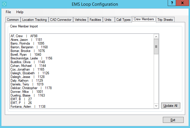
Figure 14
This list is no exception to the rest, crew members will also be kept up to date via the CAD connector services.
The Trip sheet feature within EMS Loop is configured though the configuration utility on the Trip Sheets tab as shown in Figure 15 and Figure 16. This document provides only an overview of this feature. Please see the Trip Sheet Feature document for complete configuration details.
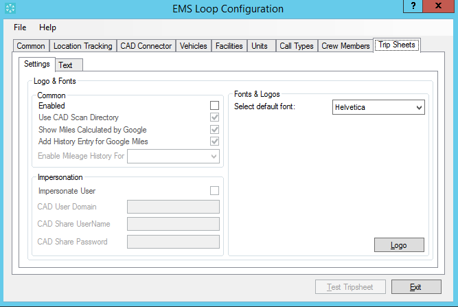
Figure 15
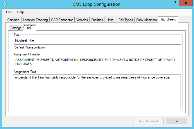
Figure 16
Once you have exported and configure the appropriate options for your system, can start the services on the “Common” tab, close the configuration tool and begin to use EMS Loop.
Application Updates
You can check for updates for the services and configuration utilities via the help menu within the configuration utility as show in Figure 17. This menu item will check to see if there is a newer version of the services and if there is will show you the changes as well as give you the option to download and install.
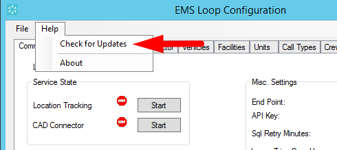
Figure 17
